
ST Microelectronics recently expanded its portfolio of STM32 microcontrollers with the new STM32F7 family. These are the new best-in-class MCUs from ST, with a Cortex-M7 core able to run up to 216Mhz (future releases will run up to 400Mhz with 2000 CoreMark index), with an internal flash up to 1Mb and 360Kb of RAM. STM32F7 is also able to run from external flash memory without performance penalty, thanks to a L1 cache (this is probably the most interesting aspect of these MCUs). STM32F7 are targeted for High-end embedded applications, especially to multimedia ones, and I think that it's far from low-budget applications and hobbyist uses. At the time of writing, these MCUs are quite pricy, ranging from 12€ to 20€/pcs for low-volume orders. This is definitely a really high price, especially if you consider that you can find around Cortex-A7 MCUs for less than 10€. But I think that the price will be dramatically reduced in the future.
ST releases two development kits to start programming with STM32F7 MCUs. One is the STM32756G-EVAL kit. It's really expensive (about €600), and it's targeted to professional users. It's with no doubt the most complete kit for this platform, but it's too expensive for me 🙂 Finally, ST has released the classical discovery kit for this platform: STM32F746G-DISCO. It's sold with a really aggressive price (about €45), and it has a lot of interesting features:
- STM32F746NGH6 microcontroller featuring 1 Mbytes of Flash memory and 340 Kbytes of RAM, in BGA216 package (yes, BGA. Don't try strange things with your board, because it's really difficult to change the micro if something goes wrong).
- On-board ST-LINK/V2-1.
- USB functions: virtual COM port, mass storage, debug port.
- 4.3-inch 480x272 color LCD-TFT with capacitive touch screen
- Camera connector
- SAI audio codec
- Audio line in and line out jack.
- Stereo speaker outputs
- Two ST MEMS microphones
- SPDIF RCA input connector
- Two pushbuttons (user and reset)
- 128-Mbit Quad-SPI Flash memory
- 128-Mbit SDRAM (64 Mbits accessible)
- Connector for microSD card
- RF-EEPROM daughterboard connector
- USB OTG HS with Micro-AB connectors
- USB OTG FS with Micro-AB connectors
- Ethernet connector compliant with IEEE-802.3-2002
- Five power supply options:
- ST LINK/V2-1 (ensure that your USB port is able to provide up to 500mAh)
- USB FS connector
- USB HS connector
- VIN from Arduino connector
- External 5 V from connector
- Power supply output for external applications: 3.3 V or 5 V
- Arduino Uno V3 connectors
STM32F746G-DISCO is currently the cheapest solution to start playing with this platform. A Nucleo-F7 is expected to be released for the end of 2015. STM32Fx-Discovery lovers, however, will be a little bit disappointed by the fact that this board doesn't expose all MCU pins to convenient pin headers, as it happens for other Discovery boards. There are only few signals routed to the Arduino-style connectors, on the bottom of the board. If you need access to other pins, probably it is better to address the more professional STM32756G-EVAL kit. However, bear in mind that STM32F7 was designed to be pin-to-pin compatible with the STM32F4 family. Moreover, consider that another interesting feature of Cortex-M7 cores it that they are binary compatible with Cortex-M4. I made a small test and I can confirm that this is true.
ST also released the STCubeF7 framework to start programming with these MCUs, with a complete HAL and tens of examples especially to test the discovery board functionalities. This is really useful to have a pleasant start with this platform.
In this article I'll show you the needed steps to start programming with this development board using a free Eclipse/GCC tool-chain. We'll create a simple app that prints a jumping string on the LCD, as shown in this video:
Even if the application is really trivial, it will give us the opportunity to set-up a complete environment to start programing with STM32F746G-DISCO board.
Assumptions and requirements
In this tutorial I’ll assume you have:
- A complete Eclipse/GCC ARM tool-chain with required plugins as described in this post or in my book about STM32 development. I’ll assume that the whole tool-chain in installed in C:\STM32Toolchain or ~/STM32Toolchain if you have a UNIX-like system.
[box type="info" align="" class="" width=""]The linked post is designed to cover the Nucleo-F4 development board. However, the process to setup the tool-chain is perfectly valid for all STM32 MCUs, and it's completely useless to repeat it here. There is only an important difference, however. At the time of writing this post (13th July 2015) the official stable release of OpenOCD is the 0.9 and it doesn't support the STM32F7 processor. We'll need to compile a "patched" version of OpenOCD able to support the STM32F746G-DISCO board. So, if you don't already have OpenOCD installed in your tool-chain, you can skip instructions about it in that tutorial, and follow the instructions here.[/box] - The latest version of STM32Cube-F7 framework from ST already downloaded and extracted.
- an STM32F746G-DISCO board. I think that it’s also simple to arrange this procedure for other boards.
Create an empty project
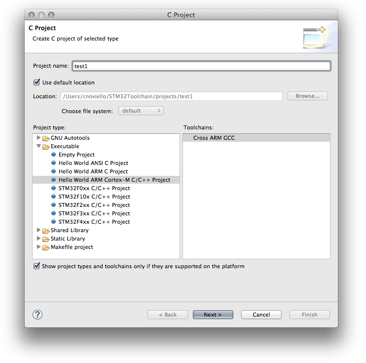
The fist step is creating a skeleton project where we’ll put HAL library from ST. So, start Eclipse and go to File->New->C Project and select “Hello World ARM Cortex-M C/C++ project. You can choose the project name you want (I chose “test1“). Click on “Next“.
 In the next step you should configure the processor characteristics. But, since the GNU ARM Plugin still lacks of a support for Cortex-M7 processors, you can completely skip this step, leaving the settings as shown in the following picture:
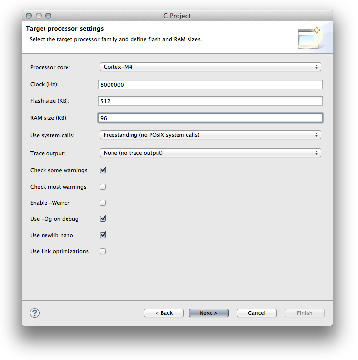 In the next step leave all parameters unchanged except for the last one: Vendor CMSIS name. Change it from DEVICE to stm32f7xx. Click on “Next“. You can leave the default parameters in the next steps. The final step is about the GCC tool-chain. You can use these values:
tool-chain name: GNU Tools for ARM Embedded Processors (arm-none-eabi-gcc)
tool-chain path: C:\STM32Toolchain\gnu-arm\4.8-2014q3\bin
Click “Finish“.
Importing STM32Cube-HAL in the Eclipse project
Ok. Now we can start importing HAL files in our project. The project generated by GNU ARM Plug-in for Eclipse is a skeleton containing Cortex Microcontroller Software Interface Standard (CMSIS) by ARM. CMSIS is a vendor-independent hardware abstraction layer for the Cortex-M processor series. It enables consistent and simple software interfaces to the processor for interface peripherals, real-time operating systems, and middleware. It’s intended to simplify software re-use and reducing the learning. However, the CMSIS package is not sufficient to start programming with an STM32 chip. It’s also required a vendor specific Hardware Abstraction Layer (HAL). This is what ST provides with its STM32Cube framework.
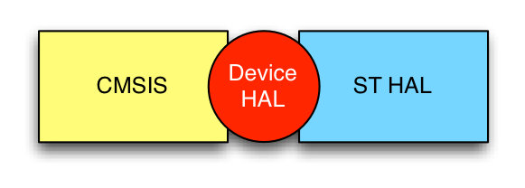
The above diagram try to explain better all the components involved in the final firmware generation. CMSIS is the universal set of features developed by ARM, and it’s common to all Cortex-M vendors (ST, ATMEL, etc). ST HAL is the hardware abstraction layer developed by ST for its specific devices, and it’s related to the STM32 family (F0, F1, etc). The Device HAL is a sort of “connector” that allows the two subsystem to talk each other. It’s a really simplified view, but this is sufficient to start programming with this architecture.
Let’s have a look to the generated project.
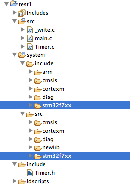
- /src and /include folders contain our “main” application. The plug-in generated a bare bone main.c file. We don’t use these files, as we’ll seen soon, but we’ll place our “main” in that folder.
- /system folder essentially contains the ARM CMSIS package.
- /system/include/stm32f7xx and /system/src/stm32f7xx are the folders where we’ll place the STM32Cube HAL.
- /ldscripts contains script for the GNU Link Editor (ld). These scripts instruct the linker to partition the memory and do several stuffs in configuring interrupts and entry point routines.
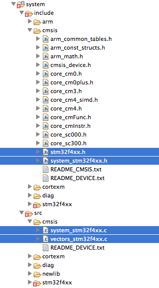
Let’s now have a look to cortexm subfolder.
The files I’ve highlighted in blue in the above picture are generated automatically by the GNU ARM Eclipse plug-in. They are part of what it’s called the Device HAL in the previous diagram. These files are substantially empty, and should be replaced by custom code, both specific for the single vendor (ST in our case), both specific for the given MCU. We are going to delete them.
So the first step is downloading the latest version of STM32Cube-F7 (or the one corresponding to your MCU) from ST web site, unpack it and place it inside the folder C:\STM32Toolchain. Once extracted, rename the folder from STM32Cube_FW_F7_V1.1.0 to STM32Cube_FW_F7.
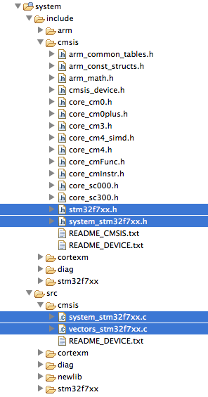
Next, go in the Eclipse project and delete the following files:
- /src/[main.c, Timer.c]
- /include/Timer.h
- /system/include/cmsis/[stm32f7xx.h,system_stm32f7xx.h]
- /system/src/cmsis/[system_stm32f7xx.c,vectors_stm32f7xx.c]
Now we have to copy HAL and other files from STM32Cube to the Eclipse project.
- HAL: go inside the STM32Cube_FW_F7/
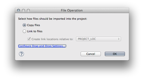
Drivers/STM32F7xx_HAL_Driver/Src folder and drag ALL the files contained to the Eclipse folder /system/src/stm32f7xx. Eclipse will ask you how to copy these files in the project folder. Select the entry “Copy”, as shown below (use always this choice):
Next, go inside the STM32Cube_FW_F7/Drivers/STM32F7xx_HAL_Driver/Inc folder and drag ALL the files contained to the Eclipse folder /system/include/stm32f7xx. - Device HAL: go inside the STM32Cube_FW_F7/Drivers/CMSIS/Device/ST/STM32F7xx/Include folder and drag ALL the files contained to the Eclipse folder /system/include/cmsis.
We now need another two files. If you remember, we’ve deleted so far two files from the generated project: system_stm32f7xx.c and vectors_stm32f7xx.c. We now need two files that do the same job (essentially, they contain the startup routines). The file vectors_stm32f7xx.c should contain the startup code when MCU resets. We’ll use an assembler file provided by ST. Go inside STM32Cube_FW_F7/Drivers/CMSIS/Device/ST/STM32F7xx/Source/Templates/gcc folder and drag the startup_stm32f746xx.s file inside the Eclipse folder /system/src/cmsis. Now, since Eclipse is not able to manage files ending with .s, we have to change the file extension to .S (capital ‘s’). So the final filename is startup_stm32f746xx.S.
Just another step. We still need a system_stm32f7xx.c file. but we need one specific for the MCU of our board. Go inside the STM32Cube_FW_F7/Drivers/CMSIS/Device/ST/STM32F7xx/Source/Templates folder and drag the system_stm32f7xx.c file inside the Eclipse folder /system/src/cmsis. - CMSIS: the STM32Cube_F7 package contains the updated release of CMSIS includes. The ones included by GNU ARM Eclipse plug-in are rather old. So, let's update them. Go inside the STM32Cube_FW_F7/Drivers/CMSIS/Device/Include folder and drag ALL the files contained to the Eclipse folder /system/include/cmsis. When prompted, ask "Yes to all" to overwrite existing files.
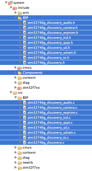
- BSP: the STM32F746G-DISCO board is a complex piece of hardware with several components (display, memories, audio devices, etc). This requires specific software modules to properly handle all those functionalities and to simplify the development process. ST grouped them in a software layer, named Board Support Package (BSP). Let's import it in our project. First create two folders named BSP into the /system/include and /system/src Eclipse folders, as shown below.

Go inside the STM32Cube_FW_F7_V1.1.0/Drivers/BSP folder and drag the Components subfolder inside the /system/include Eclipse folder. Next, go inside the STM32Cube_FW_F7_V1.1.0/Drivers/BSP/STM32746G-Discovery folder and drag all *.h files inside the /system/include/BSP Eclipse folder, and all *.c files in /system/src/BSP. The following picture shows the final result.
- Utilities: go inside the folder STM32Toolchain/STM32Cube_FW_F7 folder and drag the Utility subfolder inside the root of your Eclipse project (for the sake of completeness, I have to say that the whole content of this folder is not needed. However, to simplify this tutorial drag it entirely. When finished, you can try by your self what delete from it - Media and PC_Software subfolders are not needed).
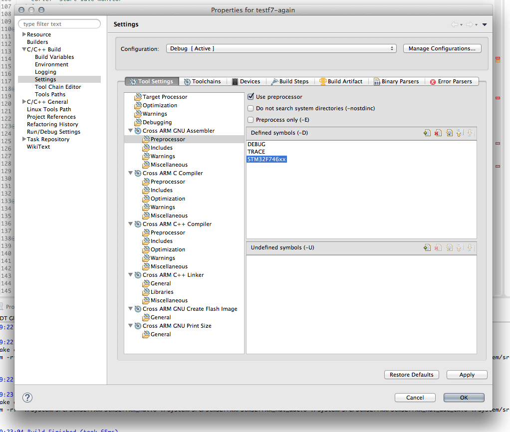
We are almost at the end of the whole procedure. We only need to setup few other things. First, we have to declare which MCU we are using defining a global macro inside the project configuration. Go inside the project properties (on the main Eclipse menu go to Project->Properties), then C/C++ Build->Settings. Click on Tool Settings and go in Cross ARM C Compiler->Preprocessor. Click on the Add icon (![]() ) and add the macro STM32F746xx. Repeat this step also for Cross ARM GNU Assembler and Cross ARM C++ Compiler sections.
) and add the macro STM32F746xx. Repeat this step also for Cross ARM GNU Assembler and Cross ARM C++ Compiler sections.
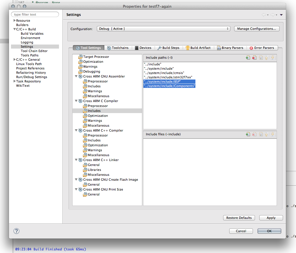
Second, we have to setup the proper Cortex core for the STM32F7. Without leaving the project settings dialog, go in Target Processor section and choose cortex-m7. Now we have to make Eclipse aware of other include folders (the folder BSP and Components we have added to the project). Go in Cross ARM C Compiler->Preprocessor and add "../system/include/BSP" and "../system/include/Components" to the Includes section, as shown below.
You can close che Project Settings dialog clicking on "OK". Finally, open the ldscripts/mem.ld file and set the FLASH and RAM memory regions in the following way :
|
1 2 3 4 5 6 |
... MEMORY { FLASH (rx) : ORIGIN = 0x08000000, LENGTH = 1024K RAM (xrw) : ORIGIN = 0x20000000, LENGTH = 320K ... |
Ok. The framework is essentially configured and we can start programming our Discovery board. The complete procedure should now use the STCubeMX tool to properly generate HAL configuration and initializations files. However, this would require a separated tutorial. To simplify this post, I'll skip this step. You can find other tutorials on my blog that show how to do this. If you are not new to STM32 programming, it will be really easy to start programming using this bare bone project.
To finish the tutorial, you can take a complete example project from my github account and copy all files contained in /src and /include folders in the corresponding Eclipse folder (or, if you want, you can import the whole project and start testing it). The main.c file is really simple. This is the excerpt of main() function:
|
70 71 72 73 74 75 76 77 78 79 80 81 82 83 84 85 86 87 88 89 90 91 92 93 94 95 96 97 98 99 100 101 102 103 |
int main(void) { /* Enable the CPU Cache */ CPU_CACHE_Enable(); /* STM32F7xx HAL library initialization */ HAL_Init(); /* Configure the system clock to 216 MHz */ SystemClock_Config(); /* Configure LCD : Only one layer is used */ LCD_Config(); /* Our main starts here */ uint16_t ypos = 0, ymax = 0; int8_t yincr = 1; BSP_LCD_SetTextColor(LCD_COLOR_WHITE); BSP_LCD_SetBackColor(LCD_COLOR_BLACK); while(1) { if(ypos == 0) { yincr = 1; ymax = BSP_LCD_GetYSize(); } else { yincr = -1; ymax = 0; } for(;yincr == 1 ? ypos < BSP_LCD_GetYSize() - Font24.Height : ypos > 0; ypos+=yincr) { BSP_LCD_DisplayStringAt(0, ypos, (uint8_t*)"Hello to everyone!", CENTER_MODE); } } } |
[box type="info" align="" class="" width=""]During the compilation process you'll see a lot of warnings to the Eclipse CDT console. To disable them, go in the Project Settings->C/C++ Build->Settings and in the Warnings sections uncheck the entry "Enable all common warnings (-Wall)".[/box]
Building OpenOCD
As I've said at the beginning of this tutorial, the current stable release of OpenOCD (0.9) can't be used to flash STM32F7 processors, since they have a different internal flash from other STM32 MCUs, which requires a different programming procedure. Fortunately, Rémi PRUD'HOMME (I think an ST engineer) has submitted a patch to OpenOCD to enable support STM32F7 family and STM32F746-DISCO board. This patch has been merged in the development OpenOCD repo. So, we can compile a custom version easily. However, I'll not give instructions on how to compile OpenOCD on the Windows platform (read this comment to download a precompiled patched version). Please, check OpenOCD instructions about this.
First let's clone the development repo of OpenOCD in this way:
|
1 2 |
$ cd ~/STM32Toolchain $ git clone http://openocd.zylin.com/p/openocd.git openocd-stm32f7 |
Next, we can compile OpenOCD in the following way:
|
1 2 3 |
$ ./bootstrap $ ./configure --enable-stlink $ make -j4 |
Once compiled, you can configure Eclipse to use this version of OpenOCD. If you are new to this procedure, please refer to this post. To start OpenOCD from command line, type:
|
1 2 |
$ cd ~/STM32Toolchain/openocd-stm32f7/tcl $ ../src/openocd -f board/stm32f7discovery.cfg |
If all is OK, these messages appears on command line:
|
1 2 3 4 5 6 7 8 9 10 11 12 13 14 15 |
Open On-Chip Debugger 0.10.0-dev-00200-gdb56a3b (2016-02-09-16:12) Licensed under GNU GPL v2 For bug reports, read http://openocd.org/doc/doxygen/bugs.html Info : The selected transport took over low-level target control. The results might differ compared to plain JTAG/SWD adapter speed: 2000 kHz adapter_nsrst_delay: 100 srst_only separate srst_nogate srst_open_drain connect_deassert_srst Info : Unable to match requested speed 2000 kHz, using 1800 kHz Info : Unable to match requested speed 2000 kHz, using 1800 kHz Info : clock speed 1800 kHz Info : STLINK v2 JTAG v24 API v2 SWIM v11 VID 0x0483 PID 0x374B Info : using stlink api v2 Info : Target voltage: 3.216820 Info : STM32F756.cpu: hardware has 8 breakpoints, 4 watchpoints |
Conclusions
With the instructions of this tutorial, you are ready to starting having fun with your new toy 🙂 I hope all instructions are clear. If they worked for you, please consider leaving a comment on the bottom. I really appreciate it 😉
53 comments
I do appreciate your great posts!
Thank you very much for all your blog entries on these topics.
Very well done!
I managed (with some difficulty) to build OpenOCD on Windows, using MSYS2.
The greeting msg from it shows:
Open On-Chip Debugger 0.9.0-rc1-dev-00004-gffb0b1a (2015-08-14-10:14)
Is that different from yours because the github code was newer when I pulled it down?
Otherwise all the same except for a few millivolts of target voltage. 🙂
Do you know why the CPU target is STM32F756 vs. 746?
Bill
Great guide! I followed it all till I stuck at the OpenOCD taks (My env. is the "crappy" Windows mention above...).
Any help or guide on how to do it? I'm using MinGW and I tried to built it there with no luck.
Thanks,
Eyal
Hi Eyal,
which kind of issues are you experiencing?
I cloned and patched the version with no problems but then when I tried to build I found myself running after additional installations, first libtool that was required by the ./bootstarp and then pkg-config-lite in order to install the libtool so I stooped this process and try to look for an alternative.
This is where I'm standing now.
Hi,
I'm not sure if this is helpful, but I found this link for the patched openocd-0.9.0 for windows.
http://gnutoolchains.com/arm-eabi/openocd/
I only did minimal changes to allow it work on my also crappy windows 7 platform.
Thank you for sharing 😉
Hi Bill,
Yes OpenOCD version differs because you pulled down a more recent release. The CPU target is different because it's stated in this way in stm32f7discovery.cfg file:
Good job! Thank you.
Thanks for the in-depth guide. It really helped me to get a development environment up and running. Currently I'm having massive issues getting the openocd to load code on the board. As far as I can see its connecting fine, writing to flash isn't working (specifically the unlock flash code). Did yours work first go? I've been debugging for a day and haven't been able to load elf files via openocd. Mine seems to fail while waiting for the flash's busy bit to go low.
openocd --debug 3 output
I've been able to load .bin files on with the stlink utility with my Windows computer, so I'm quite sure that the hardware isn't to blame. I haven't been able to find any documentation on what STLINK status codes mean, or why they would occur.
Hi Ryan,
I've to check if something is broken with the OpenOCD. I've seen that there are several update on git repository about F7 flash programming code. Probably, there is another commit to cherry pick to make it work correctly. I'll let you know soon.
Hi Ryan,
Could you check if this version of OpenOCD works for you? Follow these instructions:
$ git clone git://git.code.sf.net/p/openocd/code openocd-stm32f7

$ git fetch http://openocd.zylin.com/openocd refs/changes/54/2754/5 && git checkout FETCH_HEAD

$ ./bootstrap

$ ./configure --enable-stlink
I've checked and they work with my F7Disco. Please, let me know.
Thanks Carmine, I really appreciate the response. I'm in NZ so responses may take a while (being on the other side of the earth and all that!)
I built that version of OpenOCD and I didn't get any difference. The critical error appears to be an STLINK error while polling the flash (waiting for the busy bit to go to 0). In my test it polls twice before the st-link throws an invalid status code. If your board works, then there must be something different between our boards.
I did update the firmware on the on-board STLINK when using the STM32 ST-LINK utility. (current version is V2.J23.M9 STM32 Debug + Mass Storage). Perhaps that is the root cause? The utility can write binary files to the flash, but its useless for debugging purposes (and a huge pain because it runs only on windows).
I'm going to start investigating exactly what the return code means. My initial attempt to just continue polling the flash when the invalid return code is returned doesn't work (it appears to load .data & other elements, but the ST-Link utility shows nothing is actually written to the flash.)
This is another strange thing, because the latest ST-Link V2.1 firmware upgrade is V2.J24.M11. Try to download once again the firmware from ST web site and see if it's newer.
Another suggest I can give you is to report your problem to OpenOCD dev team. Since this patch is currently in development, your feedback may be really useful. Try to contact the developer too. You can see his E-Mail in this page.
Good afternoon! To cure this problem it is necessary to select a memory chip in the utility peredprogrammirovaniem. Add external Loader
Thank you for this tutorial. It was very helpful. I did everything up to "Building OpenOCD". When I copied over the files from the "/src" and "/include" folders to the project it highlighted several variables in the "SystemClock_Config" routine (i.e "Type 'RCC_ClkInitTypeDef' could not be resolved"). But then when I improted the whole project it didnt show any errors. Did I miss a step?
Also, when go to Project > Build Project in Eclipse - it throws me the following error:
"Program "make" not found in PATH stm32-discof7-lcdtest"
How can it be fixed?
Lastly, I am new to this, what would be my next steps? Build the program and then flash the Discovery board using the OpenOCD? Do you know of a good tutorial about how to build it on a Windows system?
This happens because Eclipse needs to rebuild index. You can force this going to Project->C/C++ Index->Rebuild.
It seems you haven't installed Build Tools. Take a look to this tutorial.
Unfortunately, this is a complex procedure under Windows. I wan't to try to write down a tutorial, but I need to find the time. Try to take a look here:
I have followed the BuildTool steps. Placed the files in that folder and added in eclipse the PATH variable. But it still compiles with that error 🙁
I installed the other option there - MinGW. Then I altered the toolchain in Eclipse: Right click on the Project -> Properties -> C/C++ Build > Tool Chain Editor. Then changed the Current Toolchain to MinGW CC.
Hi Carmine, thanks a lot for your guide, it helps me a lot to achieve the building of my project.
I'm experiencing some troubles building OpenOCD with the patch. Are you compiling it on OS X ?
I have this error when I try ./configure :
./configure: line 4515: syntax error near unexpected token
0.23'PKG_PROG_PKG_CONFIG(0.23)'./configure: line 4515:
I'm using GCC 4.2.1 to compile it, are you using the same ?
Thanks again,
Hi Nicolas,
Yes I've compiled OpenOCD under MacOS 10.9.5 without problem. Could you kindly try these other instructions in this comment?
http://www.carminenoviello.com/en/2015/07/13/started-stm32f746g-disco/#comment-57871
Thanks for your info on patching openocd.
Finally, I can get on with my STM32F7 project.
Hi Carmine,
Thank you for your good answers. Maybe you can help me. I have a custom stm32F7 target and I would like to program the flash via JTAG (I havent the STLInk on my hardware). I got the modified version of openocd and I successfully built it on my Mac. Now, to program the chip I have my script (the one I use for all my F4 targets)
Here is ma F4 script that wok like a charme
# - New interface (it replaces the old ft2232)
# - Operate with the ft4232 (0x0403 0x6011)
# - JTAG on the channel B (1)
# TMS TDI TDO CLK TMS TDI TDO CLK
# - GPIO, data = 1 0 0 0, Directions = O I O O
interface ftdi
ftdi_vid_pid 0x0403 0x6011
ftdi_channel 1
ftdi_layout_init 0x0008 0x000b
source [find target/stm32f4x.cfg]
init
reset halt
sleep 1000
stm32f2x mass_erase 0
flash write_image ./EPROM.elf
reset run
shutdown
Now, I modified it for the F7 in this way
# - New interface (it replaces the old ft2232)
# - Operate with the ft4232 (0x0403 0x6011)
# - JTAG on the channel B (1)
# TMS TDI TDO CLK TMS TDI TDO CLK
# - GPIO, data = 1 0 0 0, Directions = O I O O
interface ftdi
ftdi_vid_pid 0x0403 0x6011
ftdi_channel 1
ftdi_layout_init 0x0008 0x000b
source [find target/stm32f7x.cfg]
init
reset halt
sleep 1000
stm32f7x mass_erase 0
flash write_image ./EPROM.elf
reset run
shutdown
I have a lot of errors. It seems that the erase is OK but then, no chance!
Do you have a comment/suggestion?
Regards
Edo
Hi Edo,
unfortunately I don't have the way to do a test. I suggest you to post the full error to OpenOCD mailing list.
Thank you. You saved my life.
Quick start with stm32f746G-Disco + Eclipse. How to tune Eclipse for compiling examples from STM32CubeF7. You must install SW4STM32 from
http://www.openstm32.org/HomePage
after install stm32cubef7 download from st.com -
http://www.st.com/web/catalog/tools/FM147/CL1794/SC961/SS1743/LN1897/PF261909?s_searchtype=partnumber
and compile with presets from my video -
https://www.youtube.com/watch?v=CcIcRBWKOls
wow, thanx - pretty much worked 1st time !
Hi.
I have an STM32F7 Nucleo Board connected to an LCD like this:
PE4 ------> LTDC_B0
PE5 ------> LTDC_G0
PE6 ------> LTDC_G1
PF10 ------> LTDC_DE
PC0 ------> LTDC_R5
PA1 ------> LTDC_R2
PA2 ------> LTDC_R1
PA3 ------> LTDC_B5
PA4 ------> LTDC_VSYNC
PA5 ------> LTDC_R4
PA6 ------> LTDC_G2
PB0 ------> LTDC_R3
PE11 ------> LTDC_G3
PE12 ------> LTDC_B4
PE14 ------> LTDC_CLK
PE15 ------> LTDC_R7
PB10 ------> LTDC_G4
PB11 ------> LTDC_G5
PD10 ------> LTDC_B3
PC6 ------> LTDC_HSYNC
PC7 ------> LTDC_G6
PA8 ------> LTDC_R6
PD3 ------> LTDC_G7
PD6 ------> LTDC_B2
PG12 ------> LTDC_B1
PG13 ------> LTDC_R0
PB8 ------> LTDC_B6
PB9 ------> LTDC_B7
How can I migrate your example to my board?
Thanks
You have to change the pin-mapping inside the BSP_LCD_MspInit() function, contained in the system/src/BSP/stm32746g_discovery_lcd.c
[…] แหล่งอ้างอิง: http://www.carminenoviello.com/2015/07/13/started-stm32f746g-disco/ […]
Hi, If I want to burn a LCD example in my own board (designed by me with stm32f746vg) which LCD should I use? Do I need an LCD identical to that of Discovery board?
Can you provide me the Driver IC name or LCD model name? Help me here please. I'm stuck
All STM32F7 integrate a LTDC controller, which is a parallel 8-bit per color controller for TFT-LCD displays. This is a standard interface and it's compatibile with the most of commercial TFT displays.
The display chosen by ST in the STM32F746-Disco board is a RK043FN48H by ROCKTECH. ST provides a sort of "driver" in its HAL (https://github.com/cnoviello/stm32-discof7/blob/master/stm32-discof7-lcdtest/system/src/BSP/stm32746g_discovery_lcd.c). Is not that good, but it works. Clearly that driver can be arranged to other displays, by changing some define macros.
Currently I've bought a LCD (YL-S99816D), is this LCD compatible with the driver provided with HAL? Or do I need the exact same LCD that ST uses?
The Touch-Screen driver differs. The one used by ST is based on the FT5336, this one on a FT5206. I don't know if they can be handled in the same way. You have to check.
Hello Carmine,
I have followed all your steps but I'm getting this error while compiling in eclipse.
----------------------------------------------------------------
18:04:23 **** Incremental Build of configuration Debug for project test1 ****
make all
MAKE Version 5.41 Copyright (c) 1987, 2014 Embarcadero Technologies, Inc.
Error makefile 6: Command syntax error
Error makefile 11: Command syntax error
Error makefile 12: Command syntax error
Error makefile 13: Command syntax error
Error makefile 14: Command syntax error
Error makefile 15: Command syntax error
Error makefile 16: Command syntax error
Error makefile 17: Command syntax error
Error makefile 18: Command syntax error
Error makefile 19: Command syntax error
Error makefile 20: Command syntax error
Error makefile 21: Command syntax error
Error makefile 22: Command syntax error
Error makefile 23: Command syntax error
Error makefile 24: Command syntax error
Error makefile 25: Command syntax error
Error makefile 26: Command syntax error
Error makefile 27: Command syntax error
Error makefile 28: Command syntax error
Error makefile 29: Command syntax error
Error makefile 31: Command syntax error
Error makefile 32: Command syntax error
Error makefile 33: Command syntax error
Error makefile 34: Command syntax error
Error makefile 35: Command syntax error
Error makefile 36: Command syntax error
Error makefile 37: Command syntax error
Error makefile 38: Command syntax error
Error makefile 39: Command syntax error
Error makefile 40: Command syntax error
Error makefile 41: Command syntax error
Error makefile 42: Command syntax error
Error makefile 43: Command syntax error
Error makefile 44: Command syntax error
Error makefile 45: Command syntax error
Error makefile 46: Command syntax error
Error makefile 47: Command syntax error
Error makefile 48: Command syntax error
Error makefile 49: Command syntax error
Error makefile 50: Command syntax error
Error makefile 51: Command syntax error
Error makefile 52: Command syntax error
Error makefile 53: Command syntax error
Error makefile 54: Command syntax error
Error makefile 55: Command syntax error
Error makefile 56: Command syntax error
Error makefile 58: Command syntax error
Error makefile 99: Colon expected
Error makefile 101: Command syntax error
*** 49 errors during make ***
18:04:23 Build Finished (took 253ms)
----------------------------------------------------------------
What do you think issue is ?
It seems that the make program used by your toolchain is not compatible with the one made by GNU. Try to follow the instructions in this PDF precisely:
http://samples.leanpub.com/mastering-stm32-sample.pdf
I am trying to d'load a binary file to the dev board STM32F746NGH but get error "file not in project format"
Grazie mille! Thanks a lot for your great book (Mastering STM32) and your great extensive blogposts :-)!
Did you manage to compile, flash and run an example application from the STM32Cube_FW_F7_V1.4.0-archive (e.g. the BSP example) ? What workspace directory did you use? And how did you import the example project into Eclipse?
I have a STM32F746G-Discovery board and installed on my Windows-10 PC a Eclipse Neon - GCC ARM tool chain (according to your blogpost : http://www.carminenoviello.com/2015/07/13/started-stm32f746g-disco/ ). But now I have the problem that the BSP example from the "STM32Cube_FW_F7_V1.4.0\Projects\STM32746G-Discovery\Examples\BSP\SW4STM32\STM32746G_DISCOVERY"-archive will not compile, because of "Invalid project path, include path not found". I hope you can help me a bit further, thanks!
Hi Evert,
Unfortunately it's not easy to import F746 example projects in the Liviu Toolchains. There are a lot of "Components" to import and to configure (mostly include paths). Describing the whole import would require two or three blog posts 🙂
I suggest to download the SW4STM32 toolchain to work with those examples, because it's able to import them natively.
Thank you very much, Carmine,
that works fine indeed. I installed the STM32 toolchain from st.com into my already working Eclipse IDE and imported a project from the CubeF7 archive. I used the ST-Link Utility to flash the .bin onto the STM32F746G-discovery board and the example application worked fine :-). In the meantime I continue reading your book. Thanks again and have a nice day,
kind regards, Evert.
Hello,
I think my previous comment don't be accepted
First thanks for your great website.
I really need the STM32F746G-DISCO display datasheet (the ROCKTECH RK043FN48H-CT672B)
I try to contact ROCKTECH without success.
Can you provide me this datasheet ? This help me a lot
Thanks in advance
Best regards
Hi,
Unfortunately neither Rocktech nor ST seem to provide a datasheet for that display. I think the only option is to contact Rocktech, trying to qualify yourself as a company interesting in develop a custom device made with that display.
Many thanks Carmine
I already try this but i probably do something wrong....
For all discovery i've got, i simply found all the datasheet, i'm very disapointed with this F746G-DISCO....
Another thanks for your reply
Best regards
Hello Carmine,
Just for information i receive the datasheet from ROCKTECH, they take time because of a festival. They give me a lot of usefull information, they seem very open.
Best regards
I put the datasheet in attachmenent here :
https://my.st.com/public/STe2ecommunities/mcu/Lists/STM32Discovery/Flat.aspx?RootFolder=%2fpublic%2fSTe2ecommunities%2fmcu%2fLists%2fSTM32Discovery%2fSTM32F746G%2dDISCO%20Display%20datasheet&FolderCTID=0x01200200770978C69A1141439FE559EB459D75800084C20D8867EAD444A5987D47BE638E0F&TopicsView=https%3A%2F%2Fmy%2Est%2Ecom%2Fpublic%2FSTe2ecommunities%2Fmcu%2FLists%2FSTM32Discovery%2FAllItems%2Easpx¤tviews=34
Best regards
Hi Carmine,
Thank you for your book and articles, it's a very good source of information!
I am trying to debug with OpenOCD following the instructions you provide in your book. My board is an Nucleo-f767zi, I successfully built and installed openOCD 0.10 ( on OS X ) and also created the necessary st_nucleof7.cfg file. I can run openOCD fine, I can start the telnet connection and reset the chip, but when I try to flash it I get this error:
auto erase enabled
device id = 0x10006451
Cannot identify target as a STM32 family.
auto_probe failed
I couldn't find any way of solving that online and I kinda running out of ideas... Would you know how to solve that?
Thank you.
Best
Fabien
Okay,
I solved my problem 🙂
-> For Nucleo-f767zi boards you need the latest version of OpenOCD (from github) or you can apply this patch: http://openocd.zylin.com/#/c/3526/ and rebuild the source.
And Use the stm32f7discovery.cfg config file when you launch the debug session.
Cheers
Fabien
Hi Fabien,
Thanks for sharing 😉
I suggest you to consider to update the ST-LINK interface with the Segger dedicated JLink firmware (https://www.segger.com/jlink-st-link.html). It allows you to use the SEGGER debug tools. More stable, faster and reliable than the OpenOCD+STLINK couple. A subsequent chapter in my book will better describe all this stuff.
Ciao
Non ho nessun problema di compilazione ma seguendo il tuo esempio dell'lcd non riesco a visualizzare nulla!
Dopo aver caricato il programma nella console leggo
** Resetting Target **
shutdown command invoked
Come risolvo questa cosa?
hi,
I am using the STM32F746DÍSCO board. I tried to use openeOCD with the system workbench based on eclipse which is recommended by ST. THE OpenOCD is not able to detect the board. moreover, I tried to simply build your code and flash the board with the hex file using ST-Link utility. The code is flashed but I do not see the results. Can you help?
Hi,
It's really great tutorial and helped me a lot. I'm using STM32F746 Discovery board and I'm new to this. Now I'm trying to work with serial port communication using RS - 485 com port.
Can you suggest me some examples how I can do it?
Thanks
Hello, what passages should I run to configure openocd on stm32f7discovery in windows? Can someone help me?
I have flashed latest STM32746G-DISCO_Demo_V1.5.0.hex (C:\\STM32Cube\Repository\STM32Cube_FW_F7_V1.14.0\Projects\STM32746G-Discovery\Demonstrations\STemWin\Binary\) onto STM32F746G-DISCO board. I see display with distorted screen (lesser resolution).
I want to flash factory preloaded STM32746G-DISCO_Demo_V1.0.1.hex file. Where can I find factory preloaded software STM32746G-DISCO_Demo_V1.0.1.hex?