
[box type="info" align="alignright" class="" width=""]Please, read carefully.
Thanks to the feedbacks I have received, I reached to the conclusion that it's really hard to cover a topic like this one in the room of a blog post. So, I started writing a book about the STM32 platform. In the free book sample you can find the whole complete procedure better explained. You can download it from here.[/box]
Let's recap what we've done in the two previous parts of this series. In the first part we've configured Eclipse and GCC to build applications for the ARM-Cortex platform. We've used the GNU ARM Eclipse plug-ins to generate a minimal yet working example (a simple blinking LED app) for our STM32 Nucleo board. Next, we've used the CubeMX tool from ST to generate the right initialization code for our Nucleo. Lastly, we used ST-Link Utility to upload generated binary code on the target MCU. In the second part we've taken a deeper look in the debug topic. We've configured OpenOCD and GDB to allow step-by-step execution of our application on the Nucleo target MCU.
In this post we'll see additional debugging facilities that can be really useful during the debugging process of our firmware. First, we'll install an Eclipse plug-in that allows us to inspect internal MCU registers. Second, we'll see how to configure ARM semihosting, a capability of ARM CMSIS framework that allows to print messages coming from target MCU on the OpenOCD console.
Install EmbSysRegView
When we are doing live debugging of a firmware on the target MCU, it could be really useful to inspect MCU register, especially if we are using integrated peripherals like UART, SPI, CAN and so on. An advanced micro like the STM32F4 has a really high number of internal registers, which can have different configurations. For example, a physical PIN can have several logical functions that are enabled with different settings of dedicated registers. EMBedded SYStems REGister VIEW (below only EmbSysRegView) is an excellent Eclipse plug-in that allows to access to internal memory mapped registers of ARM Cortex MCUs. Follow this procedure to install the plug-in.
Go to Help->Eclipse Marketplace... and write "embsysregview" in the"Find" textbox. Click on "Install" when the plug-in is shown.
 In the next page check all entries and click on "Confirm".
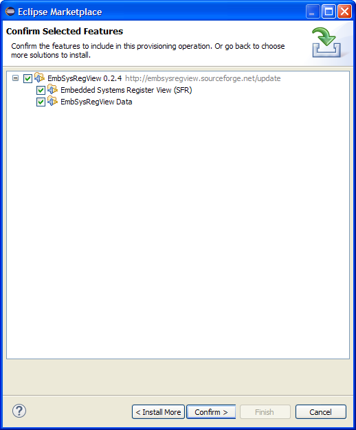
In the next page accept the license and click on "Finish". Eclipse will complete the installation after a while. Restart the IDE.
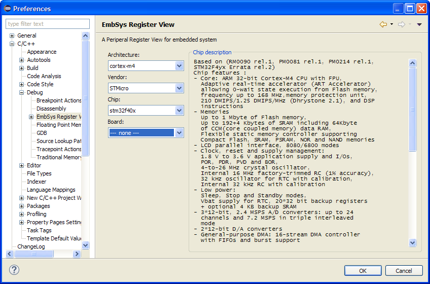
Now we need to configure EmbSysRegView for our target MCU (my Nucleo has the STM32F401RE). Go to Window->Preferences and then C/C++->Debug->EmbSys Register View and choose your micro, as shown in the following picture. [lightbox full="http://www.carminenoviello.com/wp-content/uploads/2014/12/2014-12-26-10_43_02-Preferences.png"]
[/lightbox] Next, start debugging our test1 project (the test project we've created in the fist part). To show the EmbSysRegView console, go to Window->Show View->Other.... In the selection dialog, go to Debug and then EmbSys Registers. Click on OK.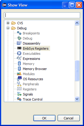 The EmbSysRegView console appears in the bottom area, as shown below. [lightbox full="http://www.carminenoviello.com/wp-content/uploads/2014/12/2014-12-26-10_48_11-.png"]
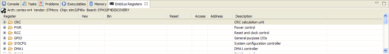 [/lightbox] The EmbSysRegView plug-in is really intuitive. Let's see an example. Open the BlinkLed.c file and insert a breakpoint at line 23, inside the function blink_led_init(), where the port A is configured so that the pin 5 is used as output (Nucleo LED LD2 is connected to that pin).
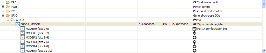
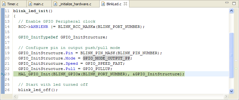 Press the run icon on the Eclipse toolbar. When the execution will automatically block at that instructions, open the EmbSysRegView console and select GPIO->GPIOA entry. By default, registers inspection is disabled (you realize this looking at the icon - it's grey when inspection is disabled, green otherwise).[lightbox full="http://www.carminenoviello.com/wp-content/uploads/2014/12/2014-12-26-11_35_53-.png"]
 [/lightbox] Click twice on the icon close to the register name. The icon switches to green. [lightbox full="http://www.carminenoviello.com/wp-content/uploads/2014/12/2014-12-26-11_40_08-.png"]
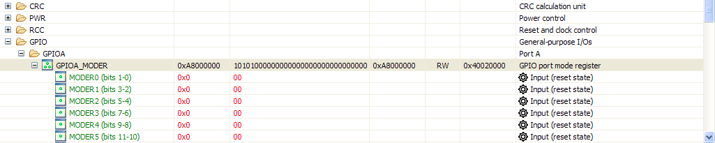 [/lightbox] Now, let's execute the instruction at line 23 clicking on Step-Over icon (
![]() ). EmbSysRegView will show that the MODER5 register has changed status. [lightbox full="http://www.carminenoviello.com/wp-content/uploads/2014/12/2014-12-26-11_44_00-.png"]
). EmbSysRegView will show that the MODER5 register has changed status. [lightbox full="http://www.carminenoviello.com/wp-content/uploads/2014/12/2014-12-26-11_44_00-.png"]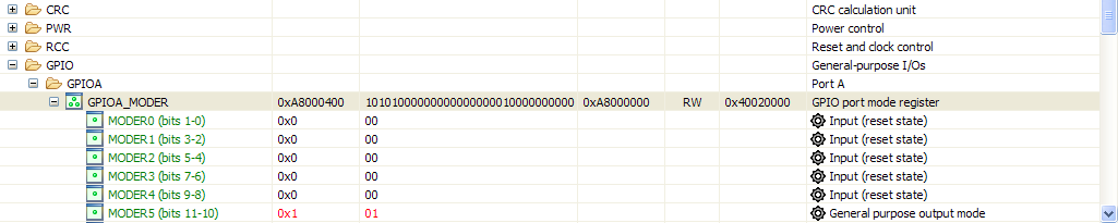 [/lightbox] [box type="info" ] The fist time you'll use EmbSysRegView, you notice a damned annoying behavior. When you do step-by-step debugging, the OpenOCD console takes the focus. This hides the EmbSysRegView console and you can't see when registers change their status. To address this, go in the OpenOCD console and click with the right mouse button. Choose "Preferences". [lightbox full="http://www.carminenoviello.com/wp-content/uploads/2014/12/2014-12-26-11_51_45-Greenshot.png"]
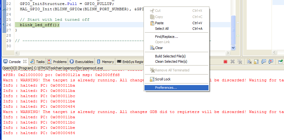 [/lightbox] In the next window, UNCHECK "Show when program writes to standard out" and "Show when program writes to standard error" entries.[/box]
If you click on a register you can change its value too. For example, if we restore the MODER5 register from 0x1 to 0x0 , the LED LD2 stops blinking, since the pin is now configured as input pin. You can modify registers value only when the firmware execution is halted.
How to print messages using ARM Semihosting
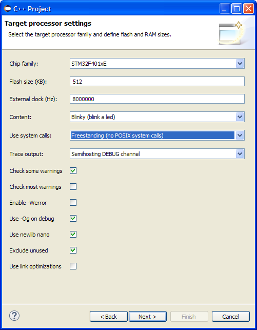
During the firmware development, it can be really useful to printout messages to understand the firmware execution. Sometimes, it's important to print the content of variables in order to understand if the program is working right. Arduino offers this functionality using the embedded virtual serial port. This operation is also possible with the Nucleo, since it provides a dedicated virtual serial port too. However, the ARM CMSIS framework (which is embedded in the STM32Cube library) provides a dedicated mechanism to this type of operation: the semihosting. ARM semihosting is a sort of remote procedure call. For example, the printf() function is called on the Nucleo MCU, but effective execution takes place on the PC connected to the board. This allows to abstract from specific hardware (video terminal, keyboard, etc) and code to control it (device drivers). The code running on the STM32 micro is "only responsible" of passing parameters to the PC through OpenOCD. Let's see an example. For the sake of simplicity, we'll start a new project, using following options during Project wizard.
When the project is generated, give a look to main.c file. You'll notice the use of trace_XXX functions. These functions use ARM semihosting to effectively print message on OpenOCD console. To test the project, we need to properly configure Nucleo clock inside configure_system_clock() in _initialize_hardware.c file and LED LD2 port in BlinkLed.h, as shown in the first part of this series. Moreover, we need to create the debug configuration as seen in the second part, but we have to add the instruction monitor arm semihosting enable to the GDB configuration, as shown in following picture:
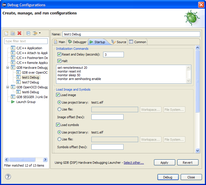 The "monitor" instruction is a prefix command that is used to transfer the remaining command from GDB to OpenOCD using 4444 TCP port. This means that OpenOCD will receive the instruction "arm semihosting enable" which enables semihosting.
Now you can start debugging the test application. You'll see the messages printed in the main() function in the OpenOCD console, as shown below: [lightbox full="http://www.carminenoviello.com/wp-content/uploads/2014/12/2014-12-27-12_24_19-Debug-test2_src_Timer.c-Eclipse.png"]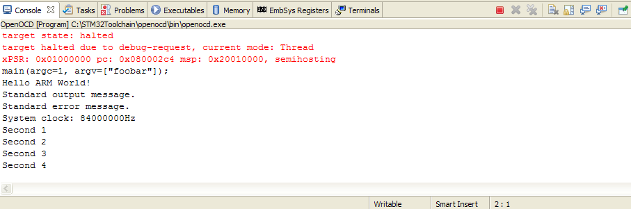 [/lightbox]
This post ends this series about on how to setup a fully working tool-chain for the STM32 Nucleo board using Eclipse, GCC, OpenOCD. Even if we specifically addressed the Nucleo development board, these instructions are still valid for the STM32 Discovery platform too. You'll only need to arrange proper configurations of specific hardware, but I think that the instructions I've given are sufficient to allow everyone to setup its working environment.
This article is part of a series made of three posts. The first part is here, the second here.
16 comments
I like the semi hosting part, thats what I m looking for 😉
Your blog was extremely helpful in helping me get my STM32F401RE up & running. Thanks. Is it possible to post a setup process for porting FreeRTOS onto STM controller using Eclipse. I haven't been really successful in getting FreeRTOS to build on eclipse, let alone port it onto hardware..
Hi,
I've successfully compiled some FreeRTOS code using Eclipse, but it isn't a trivial task. I'll try to write down a tutorial about this.
Hi,
Could you please write a tutorial on how to compile FreeRTOS Code using eclipse soon. I kind of need it urgently to start a project. Since i'm a Noob in this area, i'm struggling with it for quite some time. Thanks.
Hi!
What a shame! This tool is not provided for the STM32L1xxE !
Maybe in a next update!
Hi,
Finally the best tutorial for Nucleo. on eclipse
I used with stm32f0_discovery and this gave me the correct procedure without problems.
FreeRTOS tutorial will be great addition.
Thank You Well Done!
Hi,
thank you for this great tutorial. Got my Nucleo-F401RE running together with Eclipse on my Mac and can debug too. Only the trace-messages do not show up on my console-window. Have to try a little bit, but now I'm able to continue with the IDB04A1-tutorial 🙂
Thank you.
only to add ...
I directly changed the template for _initialize_hardware.c
At least on a Mac it can be done by editing the file /Applications/Eclipse.app/Contents/Eclipse/plugins/ilg.gnuarmeclipse.templates.stm_2.2.5.201504061754/templates/stm32f4xx_exe_c_project/src/_initialize_hardware.c
Of course, the BlinkLed.h can be edited in same way.
Hi Steve,
thank you for this feedback. It's really useful 😉
Hi, I'm using a stm32 F413ZH microncontroller with HAL libraries (mainly written to be used with c but can also be used with c++) in eclipse, actually I managed to completely configure eclipse including semihosting and debug mode(openOCD), the basic project files and also I managed to manually adapt the basic project files carmine described here to c++. So... now I can use HAL libraries in a c++ eclipse environment and test my code via OpenOCD and trace_printf trace_puts using semihosting.
Now, again I find myself stuck but this time is different. These last 7 days I have been looking for a solution to my problem and I have tried many suggestions from similar issues online but none of them has solved my problem.
Well, the thing I'm facing is a HARD FAULT when using trace_printf() using , if I use this function to print via semihosting an integer (%d) everything is okay and I can read the printed value in the OpenOCD console but when I tried to print a value with the %f formater the supposedly printed data wasn't being shown in the OpenOCD console, then I read that in order to enable the printing of floating point values I needed to add -u _printf_float to the linker flags, so after adding the flag I tried to trace_printf() a floating value, an integer value or whatever data type but using the %f formater but I keep getting a HARD FAULT
[HardFault]
Stack frame:
R0 = 00666E69
R1 = 2004FE78
R2 = 2004FF00
R3 = 00666E69
R12 = F642D800
LR = 08005DE7
PC = 08006586
PSR = 01000000
FSR/FAR:
CFSR = 00008200
HFSR = 40000000
DFSR = 0000000A
AFSR = 00000000
BFAR = 00666E69
Misc
LR/EXC_RETURN= FFFFFFF9
By debugging step by step the HARD FAULT handler is triggered after this function is called: vsnprintf()
I'm using this LINKER FLAGS -T mem.ld -T libs.ld -T sections.ld -Xlinker --gc-sections -L"../ldscripts" -Wl,-Map,"ThreePhaseSignals.map" --specs=nano.specs -u _printf_float
mem.ld
MEMORY
{
FLASH (rx) : ORIGIN = 0x08000000, LENGTH = 1536K
RAM (xrw) : ORIGIN = 0x20000000, LENGTH = 320K
/*
* Optional sections; define the origin and length to match
* the the specific requirements of your hardware. The zero
* length prevents inadvertent allocation.
*/
CCMRAM (xrw) : ORIGIN = 0x10000000, LENGTH = 0
FLASHB1 (rx) : ORIGIN = 0x00000000, LENGTH = 0
EXTMEMB0 (rx) : ORIGIN = 0x00000000, LENGTH = 0
EXTMEMB1 (rx) : ORIGIN = 0x00000000, LENGTH = 0
EXTMEMB2 (rx) : ORIGIN = 0x00000000, LENGTH = 0
EXTMEMB3 (rx) : ORIGIN = 0x00000000, LENGTH = 0
}
_sbrk.c
// ----------------------------------------------------------------------------
#include
#include
// ----------------------------------------------------------------------------
caddr_t
_sbrk(int incr);
// ----------------------------------------------------------------------------
// The definitions used here should be kept in sync with the
// stack definitions in the linker script.
caddr_t
_sbrk(int incr)
{
extern char _Heap_Begin; // Defined by the linker.
extern char _Heap_Limit; // Defined by the linker.
static char* current_heap_end;
char* current_block_address;
if (current_heap_end == 0)
{
current_heap_end = &_Heap_Begin;
}
current_block_address = current_heap_end;
// Need to align heap to word boundary, else will get
// hard faults on Cortex-M0. So we assume that heap starts on
// word boundary, hence make sure we always add a multiple of
// 4 to it.
incr = (incr + 3) & (~3); // align value to 4
if (current_heap_end + incr > &_Heap_Limit)
{
// Some of the libstdc++-v3 tests rely upon detecting
// out of memory errors, so do not abort here.
#if 0
extern void abort (void);
_write (1, "_sbrk: Heap and stack collision\n", 32);
abort ();
#else
// Heap has overflowed
errno = ENOMEM;
return (caddr_t) - 1;
#endif
}
current_heap_end += incr;
return (caddr_t) current_block_address;
}
On internet many people says that this is because printing floats consumes a lot of memory and probable the MCU is crashing due to memory overflow, so many suggestions aim to modify the linker script where stack and heap assignations are made, some others say that this hard faut is related to_sbrk.c in newlib.
I tried to adapt these solutions to my particular case but till now my problem still is not solved. I don't know if I'm badly implementing the suggestions or simply my problem is different.
Can someone help me with this? Maybe you, Carmine. Any ideas?
solved... follow this video https://www.youtube.com/watch?v=vSy4QgOP8t8&list=PLQpFqqFXr8MCxMUzun2nnqMwohhxNXWVj&index=4
Thank you for this comprehensive guide. I was wondering if you've any experience exporting from the mbed IDE programs for offline development within this toolchain. I have successfully followed your instructions here and am able to compile simple projects which I can then upload via the ST-Link onto target NUCELO boards and ST32M family chips. I have trouble when I go to export code I have developed on the mbed IDE for compiling in this toolchain (specifically, I am trying to compile in this toolchain so that I can modify the start address for use with a bootloader I developed inspired by your example bootloader from the text). Any time I attempt to compile in this toolchain I am presented with a 'make' not found error (among others). If you have had success performing this operation and have any tips they would be highly appreciated.
Hello,
The solution is in this link: https://os.mbed.com/teams/MultiTech/wiki/Using-Eclipse-and-mbed-5-for-MTS-Devices
I tested on eclipse for f401re and working...
PS: Eclipse will compile your code via mbed CLI 🙂
Meric
This article gives a beautiful introduction how to connect one nucleo board to an IDE, using a chain of free and well-maintained tools (cubemx, eclipse, openocd, stlink within nucleo, ...).
I would like to add a suggestion for a new blog article: How to connect _two_ nucleo boards to an IDE. Seriously - many embedded systems involve more than one µCs talking to each other, and it is a frequent and tedious task to get an efficient setup running. The typical challenges (with increasing difficulty) are:
1) connecting more than one nucleo to the PC so that software does not confuse which is which when programming flash (quite easy).
2) setting up debug configurations (multiple ST-Links, or is there a smarter solution?) that allow to start/stop them independently, running in parallel (quite feasible).
3) debug the two controllers in a synchronized way, i.e., so that a breakpoint on one channel stops both channels and you can inspect the states of both peers (quite demanding).
In my work/office environment, I have seen such a system running (steps 1-3), but it was with professional tools (Lauterbach etc.) for some thousands of euros. By now, I haven't found a solution in the price range of nucleo boards (i.e., at a pricing comparable to Nucleo/ST-Link)
Thankyou for the explanations you already gave us - and many thanks in advance if you choose to address this interesting issue.
Hello,
i installed the EmbSys Register View.
It does not support the stm32F446 controller.
How can i see the registers of the stm32446 ?
I read the first part, when I tried it on Windows 10 by eclipse for c/c++ embedded, but it couldn't even pass the build phrase, what maybe the reason?
the prompt was here:
https://ibb.co/pwTKMtr
I read this document "wp0001_eclipse_gcc_setup_guide.pdf", installed MSYS as it said,
then I reinstalled arm-none-eabi-gcc, and after I clicked "Build", it was prompted in "CDT Build Concole":
12:31:59 **** Incremental Build of configuration Debug for project test_NUCLEO-G474RE ****
make all
Building file: ../system/src/newlib/assert.c
Invoking: GNU Arm Cross C Compiler
arm-none-eabi-gcc -mcpu=cortex-m4 -mthumb -Og -fmessage-length=0 -fsigned-char -ffunction-sections -fdata-sections -ffreestanding -fno-move-loop-invariants -Wall -Wextra -g3 -DDEBUG -DTRACE -DOS_USE_TRACE_SEMIHOSTING_DEBUG -I"../include" -I"../system/include" -I"../system/include/cmsis" -I"../system/include/DEVICE" -std=gnu11 -MMD -MP -MF"system/src/newlib/assert.d" -MT"system/src/newlib/assert.o" -c -o "system/src/newlib/assert.o" "../system/src/newlib/assert.c"
make: *** [system/src/newlib/subdir.mk:39: system/src/newlib/assert.o] Error -1073741502
"make all" terminated with exit code 2. Build might be incomplete.
I typed "make" in CMD, it shown:
make: *** No targets specified and no makefile found. stop.
I typed "arm-none-eabi-gcc", it shown:
arm-none-eabi-gcc: fatla error: no input files
compilation terminated.